Wednesday, April 17, 2013

What is Shell and Kernel , mutex, semaphore


Category: Operating System
Both the Shell and the Kernel are the Parts of this Operating System. These Both Parts are used for performing any Operation on the System. When a user gives his Command for Performing Any Operation, then the Request Will goes to the Shell Parts, The Shell Parts is also called as the Interpreter which translate the Human Program into the Machine Language and then the Request will be transferred to the Kernel. So that Shell is just called as the interpreter of the Commands which Converts the Request of the User into the Machine Language. 
Kernel is also called as the heart of the Operating System and the Every Operation is performed by using the Kernel , When the Kernel Receives the Request from the Shell then this will Process the Request and Display the Results on the Screen. The various Types of Operations those are Performed by the Kernel are as followings:-
 
1) It Controls the State the Process Means it checks whether the Process is running or Process is Waiting for the Request of the user.
 
2) Provides the Memory for the Processes those are Running on the System Means Kernel Runs the Allocation and De-allocation Process , First When we Request for the service then the Kernel will Provides the Memory to the Process and after that he also Release the Memory which is Given to a Process.
 
3) The Kernel also Maintains a Time table for all the Processes those are Running Means the Kernel also Prepare the Schedule Time means this will Provide the Time to various Process of the CPU and the Kernel also Puts the Waiting and Suspended Jobs into the different Memory Area.
 
4) When a Kernel determines that the Logical Memory doesn’t fit to Store the Programs. Then he uses the Concept of the Physical Memory which Will Stores the Programs into Temporary Manner. Means the Physical Memory of the System can be used as Temporary Memory.
 
5) Kernel also maintains all the files those are Stored into the Computer System and the Kernel Also Stores all the Files into the System as no one can read or Write the Files without any Permissions. So that the Kernel System also Provides us the Facility to use the Passwords and also all the Files are Stored into the Particular Manner.
 
As we have learned there are Many Programs or Functions those are Performed by the Kernel But the Functions those are Performed by the Kernel will never be Shown to the user. And the Functions of the Kernel are Transparent to the user.


What are the differences between Mutex vs Semaphore? When to use mutex and when to use semaphore?
Concrete understanding of Operating System concepts is required to design/develop smart applications. Our objective is to educate  the reader on these concepts and learn from other expert geeks.
As per operating system terminology, the mutex and semaphore are kernel resources that provide synchronization services (also called as synchronization primitives). Why do we need such synchronization primitives? Won’t be only one sufficient? To answer these questions, we need to understand few keywords. Please read the posts on atomicity and critical section. We will illustrate with examples to understand these concepts well, rather than following usual OS textual description.
The producer-consumer problem:
Note that the content is generalized explanation. Practical details will vary from implementation.
Consider the standard producer-consumer problem. Assume, we have a buffer of 4096 byte length. A producer thread will collect the data and writes it to the buffer. A consumer thread will process the collected data from the buffer. Objective is, both the threads should not run at the same time.
Using Mutex:
A mutex provides mutual exclusion, either producer or consumer can have the key (mutex) and proceed with their work. As long as the buffer is filled by producer, the consumer needs to wait, and vice versa.
At any point of time, only one thread can work with the entire buffer. The concept can be generalized using semaphore.
Using Semaphore:
A semaphore is a generalized mutex. In lieu of single buffer, we can split the 4 KB buffer into four 1 KB buffers (identical resources). A semaphore can be associated with these four buffers. The consumer and producer can work on different buffers at the same time.
Misconception:
There is an ambiguity between binary semaphore and mutex. We might have come across that a mutex is binary semaphore. But they are not! The purpose of mutex and semaphore are different. May be, due to similarity in their implementation a mutex would be referred as binary semaphore.
Strictly speaking, a mutex is locking mechanism used to synchronize access to a resource. Only one task (can be a thread or process based on OS abstraction) can acquire the mutex. It means there will be ownership associated with mutex, and only the owner can release the lock (mutex).
Semaphore is signaling mechanism (“I am done, you can carry on” kind of signal). For example, if you are listening songs (assume it as one task) on your mobile and at the same time your friend called you, an interrupt will be triggered upon which an interrupt service routine (ISR) will signal the call processing task to wakeup.
General Questions:
1. Can a thread acquire more than one lock (Mutex)?
Yes, it is possible that a thread will be in need of more than one resource, hence the locks. If any lock is not available the thread will wait (block) on the lock.
2. Can a mutex be locked more than once?
A mutex is a lock. Only one state (locked/unlocked) is associated with it. However, a recursive mutex can be locked more than once (POSIX complaint systems), in which a count is associated with it, yet retains only one state (locked/unlocked). The programmer must unlock the mutex as many number times as it was locked.
3. What will happen if a non-recursive mutex is locked more than once.
Deadlock. If a thread which had already locked a mutex, tries to lock the mutex again, it will enter into the waiting list of that mutex, which results in deadlock. It is because no other thread can unlock the mutex. An operating system implementer can exercise care in identifying the owner of mutex and return if it is already locked by same thread to prevent deadlocks.
4. Are binary semaphore and mutex same?
No. We will suggest to treat them separately, as it was explained signalling vs locking mechanisms. But a binary semaphore may experience the same critical issues (e.g. priority inversion) associated with mutex. We will cover these later article.
A programmer can prefer mutex rather than creating a semaphore with count 1.
5. What is a mutex and critical section?
Some operating systems use the same word critical section in the API. Usually a mutex is costly operation due to protection protocols associated with it. At last, the objective of mutex is atomic access. There are other ways to achieve atomic access like disabling interrupts which can be much faster but ruins responsiveness. The alternate API makes use of disabling interrupts.
6. What are events?
The semantics of mutex, semaphore, event, critical section, etc… are same. All are synchronization primitives. Based on their cost in using them they are different. We should consult the OS documentation for exact details.
7. Can we acquire mutex/semaphore in an Interrupt Service Routine?
An ISR will run asynchronously in the context of current running thread. It is not recommended to query (blocking call) the availability of synchronization primitives in an ISR. The ISR are meant be short, the call to mutex/semaphore may block the current running thread. However, an ISR can signal a semaphore or unlock a mutex.
8. What we mean by “thread blocking on mutex/semaphore” when they are not available?
Every synchronization primitive will have waiting list associated with it. When the resource is not available, the requesting thread will be moved from the running list of processor to the waiting list of the synchronization primitive. When the resource is available, the higher priority thread on the waiting list will get resource (more precisely, it depends on the scheduling policies).
9. Is it necessary that a thread must block always when resource is not available?
Not necessarily. If the design is sure ‘what has to be done when resource is not available‘, the thread can take up that work (a different code branch). To support application requirements the OS provides non-blocking API.
For example POSIX pthread_mutex_trylock() API. When the mutex is not available the function will return immediately where as the API pthread_mutex_lock() will block the thread till resource is available.
References:
http://www.netrino.com/node/202
http://doc.trolltech.com/4.7/qsemaphore.html
Also compare mutex/semaphores with Peterson’s algorithm and Dekker’s algorithm. A good reference is the Art of Concurrency book. Also explore reader locks and writer locks in Qt documentation.


A mutex is a mutual exclusion semaphore, a special variant of a semaphore that only allows one locker at a time and whose ownership restrictions may be more stringent than a normal semaphore.
In other words, it's equivalent to a normal counting semaphore with a count of one and the requirement that it can only be released by the same thread that locked it.
A semaphore, on the other hand, has a count and can be locked by that many lockers concurrently. And it may not have a requirement that it be released by the same thread that claimed it (but, if not, you have to carefully track who currently has responsibility for it, much like allocated memory).
So, if you have a number of instances of a resource (say three tape drives), you could use a semaphore with a count of 3. Note that this doesn't tell you which of those tape drives you have, just that you have a certain number.
Also with semaphores, it's possible for a single locker to lock multiple instances of a resource, such as for a tape-to-tape copy. If you have one resource (say a memory location that you don't want to corrupt), a mutex is more suitable.
Equivalent operations are:
Counting semaphore          Mutual exclusion semaphore
--------------------------  --------------------------
  Claim/decrease (P)                  Lock
  Release/increase (V)                Unlock
Aside: in case you've ever wondered at the bizarre letters used for claiming and releasing semaphores, it's because the inventor was Dutch. Probeer te verlagen means to try and decrease while verhogen means to increase.


http://stackoverflow.com/questions/4039899/when-should-we-use-mutex-and-when-should-we-use-semaphore
http://www.geeksforgeeks.org/mutex-vs-semaphore/
http://www.makelinux.net/ldd3/chp-5-sect-3
http://ecomputernotes.com/fundamental/disk-operating-system/what-is-shell-and-kernel

Video Encoding and decoding and FAST MRI LWZ coing


Video Encoding and decoding .


https://www.google.co.in/search?hl=en&q=video+compression+techniques&bav=on.2,or.r_cp.r_qf.&bvm=bv.45368065,d.d2k&biw=1600&bih=732&um=1&ie=UTF-8&tbm=isch&source=og&sa=N&tab=wi&ei=AjBuUbTREMSihgebuoD4Aw#um=1&hl=en&tbm=isch&sa=1&q=video+encoder+block+diagram&oq=video+encoder&gs_l=img.1.9.0j0i5l6j0i24l3.150558.153960.0.158993.9.9.0.0.0.0.437.2360.1j3j1j2j2.9.0...0.0...1c.1.9.img.ULCbzj3ULnA&bav=on.2,or.r_cp.r_qf.&bvm=bv.45368065,d.ZG4&fp=6fcd85783a22e213&biw=1600&bih=732


http://www.macnn.com/blogs/page/19?cat=13%2F
http://www.google.co.in/imgres?um=1&hl=en&biw=1600&bih=732&tbm=isch&tbnid=cBceHKtdV6KT9M:&imgrefurl=http://www.sciencedirect.com/science/article/pii/S0923596501000029&docid=HlVyOKakRVqOkM&imgurl=http://ars.els-cdn.com/content/image/1-s2.0-S0923596501000029-gr1.gif&w=470&h=416&ei=sTBuUZvxK9OQhQev74HYDA&zoom=1&ved=1t:3588,r:29,s:0,i:174&iact=rc&dur=3646&page=2&tbnh=192&tbnw=217&start=18&ndsp=24&tx=88&ty=53
http://www.google.co.in/imgres?um=1&hl=en&biw=1600&bih=732&tbm=isch&tbnid=ScnWOjBlyQtnnM:&imgrefurl=http://www.tml.tkk.fi/Opinnot/Tik-110.551/1997/iwsem.html&docid=qQ3QUHZAgxuNBM&imgurl=http://www.tml.tkk.fi/Opinnot/Tik-110.551/1997/coding.gif&w=570&h=573&ei=-zhuUdWWLZGWhQe6p4CgCg&zoom=1&ved=1t:3588,r:8,s:0,i:103&iact=rc&dur=309&page=1&tbnh=161&tbnw=182&start=0&ndsp=16&tx=101&ty=72
http://www.tml.tkk.fi/Opinnot/Tik-110.551/1997/iwsem.html

https://www.google.co.in/webhp?sourceid=chrome-instant&ion=1&ie=UTF-8#hl=en&sclient=psy-ab&q=motion+estimation+algorithms+for+video+compression&oq=motion+estimation+algorithm&gs_l=hp.1.2.0j0i20l2j0.0.0.1.106.0.0.0.0.0.0.0.0..0.0...0.0...1c..9.psy-ab.4a-9aD3dby8&pbx=1&bav=on.2,or.r_cp.r_qf.&bvm=bv.45368065,d.d2k&fp=4b4ecafffa2b74fc&ion=1&biw=1600&bih=732

https://www.google.co.in/search?hl=en&q=sensitivity+encoding+technique+for+fast+MRI+block+diagrams&bav=on.2,or.r_cp.r_qf.&bvm=bv.45368065,d.ZWU&biw=1600&bih=732&um=1&ie=UTF-8&tbm=isch&source=og&sa=N&tab=wi&ei=K0NuUZmwLsrT7Aao_oHADQ#um=1&hl=en&tbm=isch&sa=1&q=sensitivity+encoding+++MRI+block+diagrams&oq=sensitivity+encoding+++MRI+block+diagrams&gs_l=img.12...7665.7665.2.9120.1.1.0.0.0.0.407.407.4-1.1.0...0.0...1c.1.9.img.a_6AgSRaVKk&bav=on.2,or.r_cp.r_qf.&bvm=bv.45368065,d.ZGU&fp=c5604bfd18f08ebd&biw=800&bih=366


video encoder

faculty.kfupm.edu.sa/ics/garout/Teaching/ICS202/Lecture39.ppt
http://en.wikipedia.org/wiki/Lempel%E2%80%93Ziv%E2%80%93Welch

lecture
http://www.youtube.com/course?list=ECF8C86C2E163D8E4E
https://www.youtube.com/playlist?list=PL96DDF060454FFA1A
http://www.slideshare.net/raghavendranuggu/lecture10-13923003
http://www.slideshare.net/sanjivmalik/video-compression-basics
http://www.slideshare.net/vcodex/introduction-to-h264-advanced-video-compression
http://www.springerreference.com/docs/html/chapterdbid/73079.html
http://medusa.sdsu.edu/network/


LZW coding

http://en.wikipedia.org/wiki/Lempel%E2%80%93Ziv%E2%80%93Welch


HDMI and DVI
http://en.wikipedia.org/wiki/Digital_Visual_Interface
http://en.wikipedia.org/wiki/HDMI
http://www.howtogeek.com/howto/32524/whats-the-difference-between-hdmi-and-dvi-which-is-better/


Fast Mri

http://www.sciencedirect.com/science/article/pii/S0730725X05003231
http://www.sciencedirect.com/science/article/pii/S0730725X06000853#fig1
http://www.sciencedirect.com/science/article/pii/S0730725X05003231

Public Speaking interview , introduce your self


12 Top tips for Public Speaking

Filed under Presentations , 
public-speaking-15Public speaking is probably one of the most nerve-racking experiences that any of us have to deal with.
Paul Sykes shares his top tips for standing up and speaking in public.
1.  Ask yourself the $64,000 question
What is the purpose of the speech/presentation?  You should do all that you can to get a clear answer – this will then be the baseline for you to work to.
However, if, after all your efforts, you still can’t get the answer you need, you should decline to speak.  This will save your audience the pain of sitting through a pointless presentation and save you from damaging your reputation through failing to meet their expectations.
2.  Put yourself in the place of your audience
Imagine yourself sitting where they will be and think about what you would want to know, how you would want to hear it and what would impress you.  If you want to do really well, figure out what would really impress you.
3.  Determine how long you will be speaking for
Shorter is always better than longer.  It is wise to make sure that you stop talking before your audience stops listening.  It may be tempting to think about what you want to say first and let the time be whatever it ends up being.  This is not a good idea.
Set your time; again, imagine that you are to be in the audience: how long would you expect to have to listen?  With this answer, set yourself the target to take even less time (say 20-25% less).  There are always ways of summarising and editing your ideas to communicate them in less time.
You are now ready to start to prepare your content.
4.  Gather your ideas
Look for something new to say and if you can’t find anything new, then try to find a new point of view on something familiar.  With as many ideas collected as possible, check them against the purpose of your presentation.  Prioritise them using a four-level scale: must-have, should-have, could-have and would-like-to-have.
5.  Estimate your timings
Estimate the time it might take you to speak about each idea and check how much time your talk might take including all the must-haves, then the should-haves and finally the could-haves.  It is usual to have too much material at this stage and so the would-like-to-haves will be the first to be dropped, followed by could-haves and should-haves.  If you are still dropping ideas by the time you get to must-haves you will have to work hard to reclassify your must-haves and/or reassess the time you think each idea might need.
6.  Structure is very important
Get your ideas in an order that flows and makes sense.  This might be chronological, building to a conclusion, supporting a challenging or surprising claim, or some other logical arrangement.  However, whichever you choose, you need a strong opening and an equally strong close.
7.  Concentrate on the opening and the close
The opening is what gets people’s attention and sets them up to listen to you. The close is what you will leave in their minds.
8.  Keep your notes handy
Very few people are comfortable speaking without notes.  Indeed, there is a strong argument for having notes whether you need them or not, as it shows the audience that you are not just making it up and also that you are not missing out anything important.  It doesn’t matter that this is illogical – it works!
On smallish sheets of paper or index cards write bullet-point notes that are easy to read and that show key or trigger words reminding you of the point you need to make.  Write out any direct quotes in full and feel free to read them, otherwise you should only use your notes as prompts.  Make sure that you find a way of keeping your notes in the right order; dropping them and getting them in the wrong order can be very off-putting.
9.  If you decide to use visual aids to enhance the presentation, make sure that is what they do
Never read word for word from projected slides, don’t use full sentences on your slides except in very special circumstances, and don’t feel that everything you say needs a visual aid.  Introduce pictures and diagrams to emphasise key points – it will add interest and make your points more memorable, and don’t be afraid to ask your audience to imagine a visual aid – the theatre/cinema of the mind is very powerful.
10.  Practise your presentation
Practise, preferably in front of a video camera, a mirror, or someone you trust to give you helpful feedback.  If you can, get a professional presentation coach. Not only will they be able to help you with rehearsal but they will also provide expert advice and inspiration at every other stage of the process. By the time it comes to the real event, your performance will be polished and you will be able to relax more and enjoy it.
11.  Remain calm and composed
Take a couple of deep breaths before you start.  Use pauses for effect throughout the presentation and also to compose yourself.  Make a key point, and then pause for a few seconds for the message to sink it.  You can use this as an opportunity to check your notes.  This is also a sign of a more competent speaker and will make you feel more in control.
12.  Above all, be enthusiastic, be passionate
It’s a people thing – if you don’t care about what you have to say then why should your audience?  Put yourself into your presentation.  Explain why you are excited, thrilled, delighted to be able to speak to your audience, say what this means to you, and be prepared to tell personal stories or anecdotes to illustrate your points.  It is also important that you speak up and make frequent eye contact with members of your audience.  You connect with your audience in this way, building trust and creating strong rapport.
Simply thinking about these areas will make a huge difference not only to the quality of your public presentations but also to your enjoyment. Anyone has the potential to become a much better than average presenter, which can enhance your career, social life and overall confidence.


Monday, April 15, 2013

Question and answere


H.264, Direct x acceleration lossess


h.264
http://www.h263l.com/
http://www.c21video.com/videoconferencing.html
http://en.wikipedia.org/wiki/H.264/MPEG-4_AVC
http://www.hhi.fraunhofer.de/de/kompetenzfelder/image-processing/research-groups/image-video-coding/h264mpeg4-avc.html
http://www.hhi.fraunhofer.de/de/kompetenzfelder/image-processing/research-groups/image-video-coding/svc-extension-of-h264avc.html
http://www.eetimes.com/design/signal-processing-dsp/4017613/Tutorial-The-H-264-Scalable-Video-Codec-SVC-

http://en.wikipedia.org/wiki/Scalable_Video_Coding
http://www.agoralabs.com/video-codec/h261-codec.htm


First let’s try to understand how display technology has evolved in Microsoft technology.

User32:- This provides the windows look and feel for buttons and textboxes and other UI elements. User32 lacked drawing capabilities.

GDI (Graphics device interface):- Microsoft introduced GDI to provide drawing capabilities. GDI not only provided drawing capabilities but also provided a high level of abstraction on the hardware display. In other words it encapsulates all complexities of hardware in the GDI API.

GDI+:- GDI+ was introduced which basically extends GDI and provides extra functionalities like jpg and PNG support, gradient shading and anti-aliasing. The biggest issue with GDI API was it did not use hardware acceleration and did not have animation and 3D support.

Note: - Hardware acceleration is a process in which we use hardware to perform some functions rather than performing those functions using the software which is running in the CPU.
 
DirectX :- One of the biggest issues with GDI and its extension GDI+ was hardware acceleration and animation support. This came as a biggest disadvantage for game developers. To answer and server game developers Microsoft developed DirectX. DirectX exploited hardware acceleration, had support for 3D, full color graphics , media streaming facility and lot more. This API no matured when it comes to gaming industry.

WPF :- Microsoft almost had 3 to 4 API's for display technologies , so why a need for one more display technology. DirectX had this excellent feature of using hardware acceleration. Microsoft wanted to develop UI elements like textboxes,button,grids etc using the DirectX technology by which they can exploit the hardware acceleration feature. As WPF stands on the top of directX you can not only build simple UI elements but also go one step further and develop special UI elements like Grid, FlowDocument, and Ellipse. Oh yes you can go one more step further and build animations.WPF is not meant for game development. DirectX still will lead in that scenario. In case you are looking for light animation ( not game programming ) WPF will be a choice. You can also express WPF using XML which is also called as XAML.In other words WPF is a wrapper which is built over DirectX. So let’s define WPF.
 
WPF is a collection of classes that simplify building dynamic user interfaces. Those classes include a new set of controls, some of which mimic old UI elements (such as Label, TextBox, Button), and some that are new (such as Grid, FlowDocument and Ellipse).
 

Using H.264/AVC DirectX* Video Acceleration with the Intel® G45/GM45 Express Chipsets

Categories: 

Introduction


The Intel® G45/GM45 Express Chipsets includes the next-generation Intel® Graphics Media Accelerator X4500HD with built-in support for full 1080p high definition video playback, including Blu-ray* movies. The powerful video engine provides users with smooth playback without the need for add-in cards or decoders. Acceleration is provided via the Microsoft DirectX* Video Acceleration API.

Microsoft DirectX* Video Acceleration (DXVA) is an application programming interface for speeding up the decode process of video content by using the capabilities of the graphics hardware. Software codec's and applications can use DXVA to offload certain intensive operations which frees the CPU to do additional work.

This whitepaper discusses the implementation guidelines for the decoding of H.264/AVC video using DXVA on the Intel® G45/GM45 Express Chipsets. The information is intended to be used in conjunction with the DirectX Video Acceleration Specification for H.264/AVC Decoding, available from the Microsoft Corporation. The content in this paper was developed with close coordination of the authors of Media Player Classic Home Cinema*http://mpc-hc.sourceforge.net/. All of the reference code is available for download in the SourceForge repository.

Download Entire Article


Download Using H.264/AVC DirectX* Video Acceleration with the Intel® G45/GM45 Express Chipsets [PDF 2.1MB]


lossy and lossless coding

http://books.google.co.in/books?hl=en&lr=&id=IxrjpbNH2XAC&oi=fnd&pg=PR13&dq=lossy+coding+techniques&ots=fcVq9aF9_S&sig=NnCqozovtoZYUMD_DP5dUpzT_Ns#v=onepage&q=lossy%20coding%20techniques&f=false

http://faculty.kfupm.edu.sa/ics/garout/Teaching/ICS202/Lecture39.ppt

Lossless compression techniques

Lossless compression methods may be categorized according to the type of data they are designed to compress. Some main types of targets for compression algorithms are text, executables, images, and sound. Whilst, in principle, any general-purpose lossless compression algorithm (general-purpose means that they can handle all binary input) can be used on any type of data, many are unable to achieve significant compression on data that is not of the form that they are designed to deal with. Sound data, for instance, cannot be compressed well with conventional text compression algorithms.

Most lossless compression programs use two different kinds of algorithms: one which generates a statistical model for the input data, and another which maps the input data to bit strings using this model in such a way that "probable" (e.g. frequently encountered) data will produce shorter output than "improbable" data. Often, only the former algorithm is named, while the second is implied (through common use, standardization etc.) or unspecified.

Statistical modelling algorithms for text (or text-like binary data such as executables) include:

  • Burrows-Wheeler transform (BWT; block sorting preprocessing that makes compression more efficient)
  • LZ77 (used by Deflate)
  • LZW
  • PPM
Encoding algorithms to produce bit sequences are:
  • Huffman coding (also used by Deflate)
  • Arithmetic coding 

Thursday, April 11, 2013

HARD and soft real time system


hard real-time system (immediate real-time system)


A hard real-time system (also known as an immediate real-time system) is hardware or software that must operate within the confines of a stringent deadline. The application may be considered to have failed if it does not complete its function within the allotted time span. Examples of hard real-time systems include components of pacemakers, anti-lock brakes and aircraft control systems.

Hard real-time = Pacemakers, Airplane control systems
Soft real-time = Live Video Streaming


http://www.ece.cmu.edu/~koopman/des_s99/real_time/
http://whatis.techtarget.com/definition/hard-real-time-system-immediate-real-time-system

http://www.le.ac.uk/eg/fss1/real%20time.htm

Tuesday, April 9, 2013


Digital Signal Processing (DSP) Viva Questions

DIGITAL SIGNAL PROCESSING (DSP) VIVA QUESTIONS:

1. What is sampling theorem?
2. What do you mean by process of reconstruction.
3. What are techniques of reconstructions.
4. What do you mean Aliasing? What is the condition to avoid aliasing for sampling?
5. Write the conditions of sampling.
6. How many types of sampling there?
7. Explain the statement-
t= 0:0.000005:0.05
8. In the above example what does colon (: ) and semicolon (; ) denotes.
9. What is a) Undersampling b) nyquist plot c) Oversampling.
10. Write the MATLAB program for Oversampling.
11. What is the use of command ‘legend’?
12. Write the difference between built in function, plot and stem describe the function.
13. What is the function of built in function and subplot?
14. What is linear convolution?
15. Explain how convolution syntax built in function works.
16. How to calculate the beginning and end of the sequence for the two sided controlled output?
17. What is the total output length of linear convolution sum.
18. What is an LTI system?
19. Describe impulse response of a function.
20. What is the difference between convolution and filter?
21. Where to use command filter or impz, and what is the difference between these two?
22. What is the use o function command ‘deconv’?
23. What is the difference between linear and circular convolution?
24. What do you mean by statement subplot (3,3,1).
25. What do you mean by command “mod” and where it is used?
26. What do you mean by Autocorrelation and Crosscorrelation sequences?
27. What is the difference between Autocorrelatio and Crsscorrelation.
28. List all the properties of autocorrelation and Crosscorrelaion sequence.
29. Where we use the inbuilt function ‘xcorr’ and what is the purpose of using this function?
30. How to calculate output of DFT using MATLAB?
31. What do you mean by filtic command, explain.
32. How to calculate output length of the linear and circular convolution.
33. What do you mean by built in function ‘fliplr’ and where we need to use this.
34. What is steady state response?
35. Which built in function is used to solve a given difference equation?
36. Explain the concept of difference equation.
37. Where DFT is used?
38. What is the difference between DFT and IDFT?
39. What do you mean by built in function ‘abs’ and where it is used?
40. What do you mean by phase spectrum and magnitude spectrum/ give comparison.
41. How to compute maximum length N for a circular convolution using DFT and IDFT.(what is command).
42. Explain the statement- y=x1.*x2
43. What is FIR and IIR filter define, and distinguish between these two.
44. What is filter?
45. What is window method? How you will design an FIR filter using window method.
46. What are low-pass and band-pass filter and what is the difference between these two?
47. Explain the command – N=ceil(6.6*pi/tb)
48. Write down commonly used window function characteristics.
49. What is the matlab command for Hamming window? Explain.
50. What do you mea by cut-off frequency?


Q1.- Classify signals.
Ans1.
Continuous-time, continuous amplitude (Analog Signals)
Discrete time, continuous amplitude
Continuous time, discrete amplitude
Discrete-time, discrete-amplitude
Q2.-What is the use of Random Signals?
Ans2. Random signals are used to test dynamic response statistically for very small amplitudes and time-duration.
Q3.- Classify Systems.
Ans3. Linear, stable and time-invariant.
Q4.-What do you mean by aliasing in digital signal processing? How it can be avoided?
Ans4. Aliasing refers to an effect due to which different signals become indistinguishable. It also refers to distortion in the reconstructed signal when it is reconstructed from the original continuous signal.
To avoid aliasing we can simply filter out the high frequency components of the signal by using anti-aliasing filter like optical anti-aliasing filter.
Q5. – What are the differences between a microprocessor and a DSP processor?
Ans5. DSP processors are featured to support high performance and repeatitive and intensive tasks whereas microprocessors are not application specific and they are designed to process control-oriented tasks.
Q6. – What is the convolution?
Ans6. Convolution is the technique of adding two signals in time domain. We can also do this quite easily by changing the domain of signals from time domain to frequency domain using Fast Fourier Transform (FFT).
Q7.- What is FFT?
Ans7. FFT is a fast way to calculate Discrete Fourier Transform (DFT). It is much more efficient then DFT and require less number of coding lines. Due to FFT several kind of techniques are feasible.
Q8.- What is the advantage of a Direct form II FIR over fom I?
Ans8. Direct Form II FIR filters requires half the number of delay units as much as used by Form I.
Q9.- What is interpolation and decimation?
Ans9. Interpolation is the process of increasing the sample rate in dsp whereas decimation is the opposite of this that is, it is the process of decreasing the sample rate in dsp.
10.- Difference between DFT and DTFT.
Ans10.
DFT                   DTFT
1-Limited number of samples of periodic signal 1-unlimited number of samples.
2- input is always periodic 2-input may not always be periodic
3- physically realizable 3- mathematically precise
4- frequency becomes discrete 4- frequency is continuous


http://allinterviewquestions.page.tl/DSP-Interview-Questions.htm
http://shareprogrammingtips.com/c-language-programming-tips/c-programming-interview-questions-and-answers-for-freshers/


 http://forum.jntuworld.com/showthread.php?17364-Digital-Signal-Processing-%28DSP%29-Viva-Questions

http://blog.oureducation.in/dsp-interview-questions-and-answers/


http://www.slideshare.net/PiTechnologies/embedded-sw-interview-questions

BCI and BSS

http://www.mediafire.com/view/?86fi2fzyea6yvzo
http://www.google.co.in/imgres?um=1&hl=en&sa=N&biw=1092&bih=514&tbm=isch&tbnid=wjhCnuUFa5cPNM:&imgrefurl=http://www.ece.ubc.ca/~garyb/BCI.htm&docid=3rpV2MEHCC9DSM&imgurl=http://www.ece.ubc.ca/~garyb/BCI_files/image001.gif&w=350&h=200&ei=Uy9hUZW3I8rqrAfkhYCgCw&zoom=1&ved=1t:3588,r:15,s:0,i:127&iact=rc&dur=1435&page=2&tbnh=160&tbnw=264&start=8&ndsp=12&tx=105&ty=74

http://beamsandstruts.com/bits-a-pieces/item/1026-telepathy
http://www.sheldrake.org/Articles&Papers/papers/telepathy/index.html
https://www.google.co.in/search?hl=en&q=brain+computer+interface+project+report&bav=on.2,or.r_cp.r_qf.&biw=1092&bih=514&um=1&ie=UTF-8&tbm=isch&source=og&sa=N&tab=wi&ei=2VxgUYCALof_rAekz4HwDg

http://www.brain.riken.jp/bsi-news/bsinews34/no34/research1e.html
http://www.google.co.in/imgres?um=1&hl=en&sa=N&biw=1092&bih=514&tbm=isch&tbnid=2DenclxF-CHaIM:&imgrefurl=http://soundinteractionspring2012.wordpress.com/2012/11/11/sound-and-interactive-research/&docid=-5gWQ7dpnufFVM&imgurl=http://soundinteractionspring2012.files.wordpress.com/2012/11/research0105-big-e.gif&w=750&h=569&ei=Uy9hUZW3I8rqrAfkhYCgCw&zoom=1&ved=1t:3588,r:3,s:0,i:91&iact=rc&dur=2159&page=1&tbnh=195&tbnw=258&start=0&ndsp=8&tx=86&ty=113


http://www.ece.ubc.ca/~garyb/BCI.htm
http://www.robots.ox.ac.uk/~parg/projects/bci/
http://www.google.co.in/imgres?imgurl=http://www.airlinesafety.com/editorials/Pics/Brain.gif&imgrefurl=http://www.miniscience.com/projects/ModelBrain/&h=320&w=375&sz=21&tbnid=a623v85C0dvCiM:&tbnh=90&tbnw=105&zoom=1&usg=__Tl-z2PfTtXYR4Hfd8mpp_12VxTg=&docid=M4wpvi8m-KnMvM&hl=en&sa=X&ei=dEdgUfzPJMnirAeQ9oH4DQ&ved=0CDQQ9QEwAQ&dur=1090


http://www.humanbrainproject.eu/introduction.html
http://www.popsci.com/science/article/2013-02/how-simulate-human-brain-one-neuron-time-13-billion
http://www.humanbrainproject.eu/index.html
https://www.google.co.in/#hl=en&q=phd+entrance+exam+2012-13&revid=771283090&sa=X&ei=mxlhUebQDIezrAfejYCoDw&sqi=2&ved=0CJMBENUCKAE&bav=on.2,or.r_cp.r_qf.&fp=4ab63e358afcb709&biw=1092&bih=514

https://www.google.co.in/#hl=en&sclient=psy-ab&q=brain+imaging+techniques+pdf&oq=+brain+imaging%2C&gs_l=hp.1.2.0l4.0.0.1.1356.0.0.0.0.0.0.0.0..0.0...0.0...1c..8.psy-ab.BE64wECy6XM&pbx=1&bav=on.2,or.r_cp.r_qf.&bvm=bv.44770516,d.bmk&fp=4ab63e358afcb709&biw=1092&bih=514
http://www.medphys.ucl.ac.uk/research/borl/homepages/gbranco/
http://webdocs.cs.ualberta.ca/~nray1/CMPUT466_551.htm

ML
http://www.cs.utexas.edu/~mooney/cs391L/syllabus.html
http://people.cs.pitt.edu/~milos/courses/cs2750/
 http://www.cs.ccsu.edu/~markov/ccsu_courses/570Syllabus.html
http://www.csml.ucl.ac.uk/courses/msc_ml/?q=node/143
https://www.google.co.in/url?sa=t&rct=j&q=&esrc=s&source=web&cd=9&ved=0CHEQFjAI&url=http%3A%2F%2Fweb.eecs.utk.edu%2F~parker%2FCourses%2FCS425-528-fall10%2FSyllabus.pdf&ei=wCphUZPoIIm3rAfZ4oHQBg&usg=AFQjCNHVoDJXkMzA2WdxRfoeowCQdHg4yA&sig2=tXj_1bIVh8v6aHku-H5gtQ&bvm=bv.44770516,d.bmk&cad=rja


http://www.facebook.com/photo.php?fbid=410989205646781&set=a.410986398980395.99944.300610926684610&type=3&theater

http://www.brain.riken.jp/en/faculty/details/7
http://brain.umn.edu/education.htm
http://www.sheldrake.org/Articles&Papers/papers/telepathy/


http://bbs.utdallas.edu/graduate/#phd


 http://www.foxnews.com/world/2013/01/28/projects-to-model-human-brain-and-explore-graphene-win-up-to-billion-euros-each/


http://bsrc.kaist.ac.kr/new/english/organ.htm
http://www.dibs.duke.edu/research/research-themes
http://www.tamagawa.jp/en/k12/international/
http://brain.umn.edu/education.htm

http://people.epfl.ch/mohitkumar.goel/bio?lang=en&cvlang=en

Saturday, April 6, 2013

Study on Human brain

Synthetic telepathy

Extended mind
Brain computer interface
Cognitive science: study related to brain
 blue brain


Subject need to know:
Neural communication
Neural signal processing

Machine learning
Artificial intelegent
what is neuron


Read Article ,scientific paper and journal, pattents and research paper(conference)


Wednesday, April 3, 2013

DCT

 https://docs.google.com/viewer?a=v&q=cache:3uZC5gFYPQUJ:www.dcd.zju.edu.cn/~jun/Courses/Multimedia2011.../complementary/DCT_Theory%2520and%2520Application.pdf+&hl=en&gl=in&pid=bl&srcid=ADGEEShDA_rS5clPuA-Bp1pgwTI3VBIMpzBCU1WLydBZCnWfVTk1u6z1OpXlM1dEvmPJZN4dCe7tSwxoRnk3Xs-0oTwRwkz332AdBGCO322S8ZeYlZSyKTOCKhDO1gwT226GSkd2wcCl&sig=AHIEtbSjL5oArajybDXEvKuCcahAlyOWtw


or

http://ebookbrowse.com/the-discrete-cosine-transform-dct-theory-and-application-by-syed-ali-khayam-march-10th-2003-pdf-d326144520


http://dsp.stackexchange.com/questions/13/what-is-the-difference-between-a-fourier-transform-and-a-cosine-transform
http://www.edaboard.com/thread114713.html
http://www.pcs-ip.eu/index.php/main/edu/5
http://www.cs.cf.ac.uk/Dave/Multimedia/node231.html


http://www.comp.nus.edu.sg/~wangye/papers/1.Audio_and_Music_Analysis_and_Retrieval/2000_DFT,_DCT,_MDCT,_DST_and_Signal_Fourier_Spectrum_Analysis.pdf
http://www.fftw.org/doc/Real-even_002fodd-DFTs-_0028cosine_002fsine-transforms_0029.html


www.cse.iitk.ac.in/users/avinashc/Y9111008_Y9111024_present.pdf
www.ee.ic.ac.uk/hp/staff/dmb/courses/DSPDF/00300_Transforms.pdf
http://www.svcl.ucsd.edu/courses/ece161c/handouts/DCT.pdf
http://stackoverflow.com/questions/13187992/how-to-find-all-frequencies-in-audio-with-discrete-fourier-transform

http://homepages.inf.ed.ac.uk/rbf/HIPR2/fourier.htm


research.stowers-institute.org/efg/Report/FourierAnalysis.pdf
www.dcd.zju.edu.cn/~jun/Courses/Multimedia2011.../complementary/DCT_Theory%20and%20Application.pdf


 fft


http://stackoverflow.com/questions/2551778/fft-understanding


Can somebody give a good explanation of FFT image transform How the FFT transformed image and it's Re^2+Im^2 image can be analyzed? I just want to understand something when loiking to the image and it's frequency.
share|improve this question


2 Answers


up vote 10 down vote accepted
EDIT: There is a great introduction to the concepts here.
There's a fair bit of math behind that question. In simple terms, consider a 1-D function, such as an audio clip. The fourier transform identifies the frequencies present in that signal. Each sample in the original audio clip correlates to the amplitude of the sound wave at any given point in time. In contrast, each sample in the fourier transform identifies the amplitude of a particular frequency of oscillation. For example, a pure sine wave at 1 kHz will have a fourier transform with a single spike at the 1 kHz mark. Audio waves are combinations of many different sine waves, and the fourier transform isolates which sine waves are contributing and by how much. (Note that the real explanation requires delving into complex numbers, but the foregoing gives the essence of what's going on).
The fourier transform of an image is a simple extension of the 1-D fourier transform into two dimensions, and is achieved by simply applying the 1-D transform to each row of an image, and then transforming each column of the resulting image. It produces essentially the same thing. A picture of smooth water waves travelling in a diagonal direction will transform to a series of spikes along that same diagonal.
The fourier transform is defined over continuous functions. The FFT is an technique for efficiently evaluating the fourier transform over discrete sets of data.
share|improve this answer

1  
Good answer - it might also be worth explaining the concept of spatial frequency in an image, and the interpretation of the phase and magnitude of the 2D FFT. – Paul R Mar 31 '10 at 10:33
1  
Thanks for the suggestion, @Paul. Rather than bloat the answer any more, I found a good link. – Marcelo Cantos Mar 31 '10 at 11:21

+1, good answer, I just like to add that FFT is an algorithm for efficiently computing the DFT. More on DFT: en.wikipedia.org/wiki/Discrete_Fourier_transform – Frunsi Mar 31 '10 at 11:22

@Marcelo: good link - plenty of practical examples rather than the usual dry mathematical treatment – Paul R Mar 31 '10 at 12:06

That's a great link. I've always found fourier transforms relatively easy to understand when applied to a time-signal (like audio, or a mechanical vibration), but difficult to understand with images. It didn't occur to me that it was actually pretty simple. – notJim Mar 31 '10 at 18:18
show 1 more comment

sharpening and smoothing

research.stowers-institute.org/efg/Report/FourierAnalysis.pdf


http://fourier.eng.hmc.edu/e161/lectures/gradient/node5.html
http://homepages.inf.ed.ac.uk/rbf/HIPR2/log.htm
http://www.cambridgeincolour.com/tutorials/image-sharpening.htm


https://www.google.co.in/search?hl=en&newwindow=1&q=image+sharpening+and+smoothing&oq=sharpening+and+smoothing&gs_l=serp.1.1.0i22i30l5.3624049.3630132.0.3635406.47.18.0.0.0.10.482.1504.11j3j4-1.15.0...0.0...1c.1.7.serp.xoTJwvsI_so


From taking better pictures on a camera to improved medical diagnostics, imaging applications touch every aspect of daily life. The common thread between all these applications is the requirement to capture data from a sensor and process it at high speed to handle the large volume of data produced by sensors as well as to provide superb user experience in devices such as cameras.
Synphony allows the capture and design of hardware implementations of imaging algorithms in C, the same untimed language commonly used during algorithm development and exploration. By taking care of the complex task of extracting parallelism and creating high performance hardware,the Synphony allows the designer to focus on the key differentiator – the algorithm and the overall architecture to achieve the final image look that will captivate customers.
Typical Imaging Designs synopsys
The Synphony team has successfully worked with designers to complete a wide variety of complex imaging applications with excellent quality of results. Example designs that have been done or can be done using Synphony C Compiler includes:
  • Image capture: Bayer to RGB conversion, color space conversion, sharpening and smoothing, smile and face detection and red-eye reduction
  • Medical imaging: Algorithms like back-projection and FFT/IFFT Compression/Decompression: Commonly used algorithms in compression such as DCT/IDCT, wavelet coding, Huffman coding; JPEG, JPEG2000 and lossless JPEG pipelines
  • Image processing and enhancements: Scaling, sharpening, noise reduction, edge smoothing, background/foreground separation and film grain insertion
  • Image analysis for security, automotive, medical and industrial applications: Edge detection, face recognition, feature detection, lane/sign detection and object recognition
  • Printer pipelines: Color transform, halftoning, scaling, compression/decompression of halftoned images and resolution enhancement

ompass Gradient Operations

The following compass operators can detect edges of a particular direction:
\begin{displaymath}\left[ \begin{array}{rrr} -1 & 0 & 1  -1 & 0 & 1  -1 & 0 ...
...& 0  1 & 0 & -1  0 & -1 & -1
\end{array} \right], \;\;\;
\end{displaymath}


\begin{displaymath}\left[ \begin{array}{rrr} 1 & 0 & -1  1 & 0 & -1  1 & 0 &...
...} -1 & -1 & 0  -1 & 0 & 1  0 & 1 & 1
\end{array} \right]
\end{displaymath}

Other compass operators
\begin{displaymath}
\left[ \begin{array}{rrr} 1 & 1 & 1  1 & -2 & 1  -1 & -...
...& 1  0 & 0 & 0  -1 & -2 & -1
\end{array} \right], \;\;\;
\end{displaymath}

For all convolution kernels above, the sum of all elements is zero, i.e., the output from a homogeneous image region is zero. If the orientation of the edge is not needed, we run these compass operators in all directions and find if the maximum of them is greater than a threshold value. edge_detection_4_dir.gif
Higher angular resolution can be achieved by increase the mask size. The two kernels below are for 30 and 60 degrees, respectively:
\begin{displaymath}
\left[ \begin{array}{rrrrr} 1 & 1 & 1 & 1 & 1  -.32 & .78 ...
...2 & .78 & 1 \\
-1 & -1 & -1 & -.32 & 1
\end{array} \right]
\end{displaymath}


home left right up

---

Laplacian/Laplacian of Gaussian


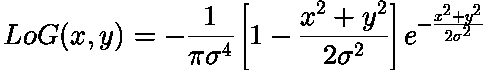
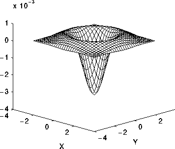
Common Names: Laplacian, Laplacian of Gaussian, LoG, Marr Filter
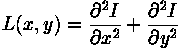
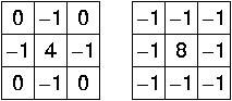
Brief Description

The Laplacian is a 2-D isotropic measure of the 2nd spatial derivative of an image. The Laplacian of an image highlights regions of rapid intensity change and is therefore often used for edge detection (see zero crossing edge detectors). The Laplacian is often applied to an image that has first been smoothed with something approximating a Gaussian smoothing filter in order to reduce its sensitivity to noise, and hence the two variants will be described together here. The operator normally takes a single graylevel image as input and produces another graylevel image as output.

How It Works

The Laplacian L(x,y) of an image with pixel intensity values I(x,y) is given by:
Eqn:eqnlog1
This can be calculated using a convolution filter.
Since the input image is represented as a set of discrete pixels, we have to find a discrete convolution kernel that can approximate the second derivatives in the definition of the Laplacian. Two commonly used small kernels are shown in Figure 1.


Figure 1 Two commonly used discrete approximations to the Laplacian filter. (Note, we have defined the Laplacian using a negative peak because this is more common; however, it is equally valid to use the opposite sign convention.)

Using one of these kernels, the Laplacian can be calculated using standard convolution methods.
Because these kernels are approximating a second derivative measurement on the image, they are very sensitive to noise. To counter this, the image is often Gaussian smoothed before applying the Laplacian filter. This pre-processing step reduces the high frequency noise components prior to the differentiation step.
In fact, since the convolution operation is associative, we can convolve the Gaussian smoothing filter with the Laplacian filter first of all, and then convolve this hybrid filter with the image to achieve the required result. Doing things this way has two advantages:
  • Since both the Gaussian and the Laplacian kernels are usually much smaller than the image, this method usually requires far fewer arithmetic operations.
  • The LoG (`Laplacian of Gaussian') kernel can be precalculated in advance so only one convolution needs to be performed at run-time on the image.
The 2-D LoG function centered on zero and with Gaussian standard deviation Eqn:eqnsigma has the form:
Eqn:eqnlog2
and is shown in Figure 2.


Figure 2 The 2-D Laplacian of Gaussian (LoG) function. The x and y axes are marked in standard deviations (Eqn:eqnsigma).

A discrete kernel that approximates this function (for a Gaussian Eqn:eqnsigma = 1.4) is shown in Figure 3.


Figure 3 Discrete approximation to LoG function with Gaussian Eqn:eqnsigma = 1.4

Note that as the Gaussian is made increasingly narrow, the LoG kernel becomes the same as the simple Laplacian kernels shown in Figure 1. This is because smoothing with a very narrow Gaussian (Eqn:eqnsigma < 0.5 pixels) on a discrete grid has no effect. Hence on a discrete grid, the simple Laplacian can be seen as a limiting case of the LoG for narrow Gaussians.

Guidelines for Use

The LoG operator calculates the second spatial derivative of an image. This means that in areas where the image has a constant intensity (i.e. where the intensity gradient is zero), the LoG response will be zero. In the vicinity of a change in intensity, however, the LoG response will be positive on the darker side, and negative on the lighter side. This means that at a reasonably sharp edge between two regions of uniform but different intensities, the LoG response will be:
  • zero at a long distance from the edge,
  • positive just to one side of the edge,
  • negative just to the other side of the edge,
  • zero at some point in between, on the edge itself.
Figure 4 illustrates the response of the LoG to a step edge.


Figure 4 Response of 1-D LoG filter to a step edge. The left hand graph shows a 1-D image, 200 pixels long, containing a step edge. The right hand graph shows the response of a 1-D LoG filter with Gaussian Eqn:eqnsigma = 3 pixels.

By itself, the effect of the filter is to highlight edges in an image.
For example,
wdg4
is a simple image with strong edges.
The image
wdg4log1
is the result of applying a LoG filter with Gaussian Eqn:eqnsigma = 1.0. A 7×7 kernel was used. Note that the output contains negative and non-integer values, so for display purposes the image has been normalized to the range 0 - 255.
If a portion of the filtered, or gradient, image is added to the original image, then the result will be to make any edges in the original image much sharper and give them more contrast. This is commonly used as an enhancement technique in remote sensing applications.
To see this we start with
fce2
which is a slightly blurry image of a face.
The image
fce2log1
is the effect of applying an LoG filter with Gaussian Eqn:eqnsigma = 1.0, again using a 7×7 kernel.
Finally,
fce2log2
is the result of combining (i.e. subtracting) the filtered image and the original image. Note that the filtered image had to be suitable scaled before combining in order to produce a sensible enhancement. Also, it may be necessary to translate the filtered image by half the width of the convolution kernel in both the x and y directions in order to register the images correctly.
The enhancement has made edges sharper but has also increased the effect of noise. If we simply filter the image with a Laplacian (i.e. use a LoG filter with a very narrow Gaussian) we obtain
fce2lap2
Performing edge enhancement using this sharpening image yields the noisy result
fce2lap1
(Note that unsharp filtering may produce an equivalent result since it can be defined by adding the negative Laplacian image (or any suitable edge image) onto the original.) Conversely, widening the Gaussian smoothing component of the operator can reduce some of this noise, but, at the same time, the enhancement effect becomes less pronounced.
The fact that the output of the filter passes through zero at edges can be used to detect those edges. See the section on zero crossing edge detection.
Note that since the LoG is an isotropic filter, it is not possible to directly extract edge orientation information from the LoG output in the same way that it is for other edge detectors such as the Roberts Cross and Sobel operators.
Convolving with a kernel such as the one shown in Figure 3 can very easily produce output pixel values that are much larger than any of the input pixels values, and which may be negative. Therefore it is important to use an image type (e.g. floating point) that supports negative numbers and a large range in order to avoid overflow or saturation. The kernel can also be scaled down by a constant factor in order to reduce the range of output values.

Common Variants

It is possible to approximate the LoG filter with a filter that is just the difference of two differently sized Gaussians. Such a filter is known as a DoG filter (short for `Difference of Gaussians').
As an aside it has been suggested (Marr 1982) that LoG filters (actually DoG filters) are important in biological visual processing.
An even cruder approximation to the LoG (but much faster to compute) is the DoB filter (`Difference of Boxes'). This is simply the difference between two mean filters of different sizes. It produces a kind of squared-off approximate version of the LoG.

Interactive Experimentation

You can interactively experiment with the Laplacian operator by clicking here.
You can interactively experiment with the Laplacian of Gaussian operator by clicking here.

Exercises

  1. Try the effect of LoG filters using different width Gaussians on the image
    ben2
    What is the general effect of increasing the Gaussian width? Notice particularly the effect on features of different sizes and thicknesses.
  2. Construct a LoG filter where the kernel size is much too small for the chosen Gaussian width (i.e. the LoG becomes truncated). What is the effect on the output? In particular what do you notice about the LoG output in different regions each of uniform but different intensities?
  3. Devise a rule to determine how big an LoG kernel should be made in relation to the Eqn:eqnsigma of the underlying Gaussian if severe truncation is to be avoided.
  4. If you were asked to construct an edge detector that simply looked for peaks (both positive and negative) in the output from an LoG filter, what would such a detector produce as output from a single step edge?

References

R. Haralick and L. Shapiro Computer and Robot Vision, Vol. 1, Addison-Wesley Publishing Company, 1992, pp 346 - 351.
B. Horn Robot Vision, MIT Press, 1986, Chap. 8.
D. Marr Vision, Freeman, 1982, Chap. 2, pp 54 - 78.
D. Vernon Machine Vision, Prentice-Hall, 1991, pp 98 - 99, 214.

Local Information

Specific information about this operator may be found here.
More general advice about the local HIPR installation is available in the Local Information introductory section.

---

home left right up

©2003 R. Fisher, S. Perkins, A. Walker and E. Wolfart.

Valid HTML 4.0!