MIT Lincoln Laboratory researchers introduce students to radar engineering
During MIT's Independent Activity Period (IAP) between the fall 2010 and spring 2011 semesters, twenty-six students responded "yes" to this question posed in the course description for an activity led by MIT Lincoln Laboratory engineers: "Are you interested in building and testing your own imaging radar system?"
In just three weeks, the students worked in teams to design, fabricate, and test a laptop-based radar sensor that was capable of measuring Doppler and range, and of forming synthetic aperture radar (SAR) images. The teams received class instruction on the fundamentals of radar and SAR imaging, and kits from which to develop their systems. To their surprise, the kits contained coffee cans, which Dr. Gregory Charvat, one of the course instructors, explains were to be used as transmit and receive antennas:
"In developing the course, we were unable to find a kit that offered a suitable level of sophistication. All the commercial kits we could find were simple Doppler speed guns. So I designed a kit that is a coherent frequency-modulated continuous-wave radar capable of measuring Doppler versus time and range versus time, as well as performing SAR imaging. The kit supplies coffee cans as antennas to reduce cost." The kits also contained mini-circuit parts and a solderless breadboard that would allow quick fabrication and easy modification. The systems built from the kits run on AA batteries and use a laptop audio input for digitization. Data were recorded as .wav files and then processed in MATLAB computational software.
 An example small radar system built from the kit of parts and connected to a laptop.
"One of the things I really grew to appreciate through the radar building process was how accurate a hand-built coffee-can radar could be," says Paresh Malalur, an MIT graduate student who took the course. "The system was much more responsive than I was expecting. For instance, one of the experiments we did was to measure the Doppler shift on a free-falling object (a book wrapped in foil). I was shocked to see the frequency ramp up in a perfectly linear manner over time. I was expecting a coffee cantenna system to have much higher noise and much less sensitivity."
During the three weeks, students performed in-class experiments with the radar systems they built. They also conducted field experiments (in Cambridge) such as measuring the speed of a passing car or plotting the range of a moving target. The culminating activity of the course was a contest to form the most detailed and creative SAR image. The winning image, created by Tony Hyun Kim, Nevada Sanchez, and Paresh Malahur, is of the outdoor steel sculpture La Grande Voile (Great Sail), designed by Alexander Calder and installed outside the List Visual Arts Center at MIT.
An example small radar system built from the kit of parts and connected to a laptop.
"One of the things I really grew to appreciate through the radar building process was how accurate a hand-built coffee-can radar could be," says Paresh Malalur, an MIT graduate student who took the course. "The system was much more responsive than I was expecting. For instance, one of the experiments we did was to measure the Doppler shift on a free-falling object (a book wrapped in foil). I was shocked to see the frequency ramp up in a perfectly linear manner over time. I was expecting a coffee cantenna system to have much higher noise and much less sensitivity."
During the three weeks, students performed in-class experiments with the radar systems they built. They also conducted field experiments (in Cambridge) such as measuring the speed of a passing car or plotting the range of a moving target. The culminating activity of the course was a contest to form the most detailed and creative SAR image. The winning image, created by Tony Hyun Kim, Nevada Sanchez, and Paresh Malahur, is of the outdoor steel sculpture La Grande Voile (Great Sail), designed by Alexander Calder and installed outside the List Visual Arts Center at MIT.
An example small radar system built from the kit of parts and connected to a laptop. The winning SAR image. To the right is the actual sculpture that is depicted in the image. The winning SAR image. To the right is the actual sculpture that is depicted in the image. | 
Alexander Calder, La Grande Voile, 1968. Photo courtesy of MIT List Visual Arts Center.
|
"This is one of the most beautiful SAR images I have seen, and it was made by a radar built of coffee cans and that plugs into a laptop audio input," says Charvat.
 The winners of the SAR imaging contest were the team of Paresh Malalur, Nevada Sanchez, and Tony Hyun Kim, holding their “radar” design, the Cantenna Radar. Shown behind the team are Dr. Eric Evans (left), Director of Lincoln Laboratory, who presented the trophy (held by Kim); Dr. Gregory Charvat (center) and Jonathan Williams (right), both instructors for the course.
The objective of the course was to generate student interest in applied electromagnetics, signal processing, and RF systems. The field experiments and the imaging contest were the incentives for students to configure their radars to work properly and to delve into the subjects more deeply. "The more radar experiments they attempted, the deeper their questions became," says Charvat.
The course, the full tile of which is "Build a Small Radar System Capable of Sensing Range, Doppler, and Synthetic Aperture Radar Imaging," was enthusiastically received by the students, who dedicated outside-the-classroom hours to conducting field trials.
"A few of the students were actively blogging as they were taking the course so we were able to watch their enthusiasm for the class grow as their radar started to come together," says Jonathan Williams, another instructor for the course. "We could also tell the enthusiasm students had for the class by how much work they did beyond the scope of the class. Not only did they build and test the radar from a kit of parts, some of them made significant improvements to the radar." Among those improvements were the development of a real-time data viewer that allowed a student to record live videos of data as they were being taken and the discovery of a simple algorithm that cleaned up "messy," real-world data.
In addition to Charvat and Williams, Drs. Alan Fenn, Stephen Kogon, and Jeffrey Herd served as instructors or co-developers of the activity. Kim, another MIT graduate student, was impressed by the curriculum these engineers developed. "The teaching staff emphasized the historical context that surrounded the development of radar technology. As our team implemented and tested our rudimentary radar system, we could appreciate the implications of our design choices not only by their technical performance, but also in terms of their broader societal and historical impact."
On the final class day, Dr. Eric Evans, Director of Lincoln Laboratory, Dr. Marc Bernstein, Associate Director, and Dr. Robert Shin, Head of the ISR and Tactical Systems Division, judged the SAR imaging contest. The trophy, featuring a coffee can antenna, was presented by Evans.
All nine teams of students were able to achieve Doppler/time and range/time measurements with their radar systems, and seven teams achieved SAR imaging.
 |  |
| The graph on the left shows the Doppler vs. time measurements for a pendulum. The graph on the right shows range vs. time measurements of a student running in the basement MIT Building 5. | |
Continuous Wave Radar
Principle of Operation
As opposed to pulsed radar systems, continuous wave (CW) radar systems emit electromagnetic radiation at all times. Conventional CW radar cannot measure range because there is no basis for the measurement of the time delay. Recall that the basic radar system created pulses and used the time interval between transmission and reception to determine the target's range. If the energy is transmitted continuously then this will not be possible.CW radar can measure the instantaneous rate-of-change in the target's range. This is accomplished by a direct measurement of the Doppler shift of the returned signal. The Doppler shift is a change in the frequency of the electromagnetic wave caused by motion of the transmitter, target or both. For example, if the transmitter is moving, the wavelength is reduced by a fraction proportional to the speed it is moving in the direction of propagation. Since the speed of propagation is a constant, the frequency must increase as the wavelength shortens. The net result is an upwards shift in the transmitted frequency, called the Doppler shift.
Figure 1. Doppler shift from moving transmitter
Likewise, if the receiver is moving opposite to the direction of propagation, there will a increase in the received frequency. Furthermore, a radar target which is moving will act as both a receiver and transmitter, with a resulting Doppler shift for each. The two effects caused by the motion of the transmitter/receiver and target can be combined into a net shift the frequency. The amount of shift will depend of the combined speed of the transmitter/receiver and the target along the line between them, called the line-of-sight(LOS).
Figure 2. Calculating the relative speed in the line-of-sight.
The Doppler shift can be calculated with knowledge of the transmitter/receiver and target speeds, here designated as s1 and s2 respectively, and the angles between their direction of motion and the line-if-sight, designated q1 and q2. The combined speed in the line-of-sight is
s = s1 cosq1 + s2 cosq2 .
This speed can also be interpreted as the instantaneous rate of change in the range, or range rate. As long as the problem is confined to two-dimensions, the angles also have simple interpretations: q1 = the relative bearing to the target. The difference between the course of the transmitter/receiver and the true bearing to the target. This follows the old nautical rule:
Relative Bearing = True Bearing - Heading
Due to the characteristics of the cosine function, it makes no difference whether angle is positive or negative (strictly speaking, relative bearings are always positive and range from 0 to 3590). q2 = the target angle (relative bearing of transmitter/receiver from target). Computed in an identical manner as the relative bearing, except that the target's course is substituted for the heading and the reciprocal bearing is used instead of the true bearing to the target. The reciprocal bearing is found by:
Reciprocal Bearing = True Bearing 1800
Again, it does not matter is this result is positive, negative or even beyond 3600, although the proper result would be in the range of 0-3590. Assuming that the range rate is known the shift in returned frequency is
Df = 2s/l
where l is the wavelength of the original signal. As an example, the Doppler shift in an X-band (10 GHz) CW radar will be about 30 Hz for every 1 mph combined speed in the line-of-sight.
Example: speed gun.
Police often use CW radar to measure the speed of cars. What is actually measured is the fraction of the total speed which is towards the radar. If there is some difference between the direction of motion and the line-of-sight, there will be error. Fortunately for speeders, the measured speed is always lower than the actual.
CW radar systems are used in military applications where the measuring the range rate is desired. Of course, range rate can be determined from the basic pulsed radar system by measuring the change in the detected range from pulse to pulse. CW systems measure the instantaneous range rate, and maintain continuous contact with the target.
Frequency Modulated Continuous Wave (FMCW) Radar
It is also possible to use a CW radar system to measure range instead of range rate by frequency modulation, the systematic variation of the transmitted frequency. What this does in effect is to put a unique "time stamp" on the transmitted wave at every instant. By measuring the frequency of the return signal, the time delay betweentransmission and reception can be measure and therefore the range determined as before. Of course, the amount of frequency modulation must be significantly greater than the expected Doppler shift or the results will be affected.
The simplest way to modulate the wave is to linearly increase the frequency. In other words, the transmitted frequency will change at a constant rate.
Figure 3. FMCW theory of operation.
The FMCW system measures the instantaneous difference between the transmitted and received frequencies, Df. This difference is directly proportional to the time delay, Dt, which is takes the radar signal to reach the target and return. From this the range can be found using the usual formula, R = cDt/2. The time delay can be found as follows:
Dt = T Df/(f2-f1) where:
f2 = maximum frequency
f1 = minimum frequency
T = period of sweep from f1 to f2,
and Df = the difference between transmitted and received.
There is a slight problem which occurs when the sweep resets the frequency and the frequency difference becomes negative (as shown in the plot of Df vs. time). The system uses a discriminator to clip off the negative signal, leaving only the positive part, which is directly proportional to the range. Here is a system diagram:
 Figure 4. FMCW block diagram.
Combining these equations into a single form for the range
R = 2cTDf/(f2 - f1)
where Df is the difference between the transmitted and received frequency (when both are from the same sweep, i.e. when it is positive).
Another way to construct a FMCW system, is to compare the phase difference between the transmitted and received signals after they have been demodulated to receiver the sweep information. This system does not have to discriminate the negative values of Df. In either case however, the maximum unambiguous range will still be determined by the period, namely
Runamb = cT/2
FMCW systems are often used for radar altimeters, or in radar proximity fuzes for warheads. These systems do not have a minimum range like a pulsed system. However, they are not suitable for long range detection, because the continuous power level they transmit at must be considerably lower than the peak power of a pulsed system. You may recall that the peak and average power in a pulse system were related by the duty cycle,
Pave = DC *Ppeak
For a continuous wave system, the duty cycle is one, or alternatively, the peak power is the same as the average power. In pulsed systems the peak power is many times greater than the average.
4GHz 200mW Low-Noise FMCW Radar Front-end


This is a special low-noise high-power version of 94GHz FMCW radar front-end, that is designed for traffic control applications. The primary example of that application is airport ground control radar systems.
Click here to see 200mW front-end block-schema in PDF format.
We propose the following variants of 200mW radar front-end shipment:
- with row analog output
- with row digital output
- with processed digital output (angle, distance and speed of a target)
- with row analog output
- with row digital output
- with processed digital output (angle, distance and speed of a target)
Important: we advise our customers to purchase radar 200mW front-end with antenna to get them tuned as a whole unit. The reason for that is as following. Compare to 10mW version of the 94GHz FMCW radar front-end, this 200mW has a special circuitry design features to reduce noise factors. In according of that design, to reduce noise, the radar front end has to be adjusted with its antenna as the whole unit. Please read the following explanation which is illustrating these design features:

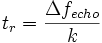
Fig. 1. General block schema of FMCW radar output
In this figure:
P1 – the power leakage through output circulator (isolation is approximately 30 dB);
P2 – the reflected power from the antenna (Antenna VSWR is less 1.13:1).
P1 – the power leakage through output circulator (isolation is approximately 30 dB);
P2 – the reflected power from the antenna (Antenna VSWR is less 1.13:1).
In general, the noise figure of receiver of FMCW radar front-end depends not only on receiver quality itself but also on amplitude noises of transmitter channel because transmitter power penetrates into the receiver. The penetrating power consists of two parts: the first one is a leakage of power through output circulator ports (path P1 in the fig.1) and the second one is reflected power from antenna (P2).
The leakage of mm-wave power from transmitter to receiver leads to increasing of receiver noise figure and decrease its sensitivity. In any radar front-end module with the design similar to ELVA FMCW-10/94/200/200 the influence of leakage of transmitter power on noise figure gets considerable high when the transmitter power is more then approximately 10 mW. As experiments in ELVA lab shows - for 200 mW output power of FMCW-10/94/200/200 model the increasing of the noise figure can be from 13 dB to 25…30 dB. That's why it is necessary to make an attempt for counter-measure against the increasing of Noise figure.
The straightaway approach to decrease the leakage of transmitter power to receiver is to use output circulator with higher isolation and antenna with lower VSWR. But ELVA experience as producer of mm-wave components shows that it is very difficult task.
That's why ELVA proposed another approach: the problem can be solved by adding P1 to P2signals in such way that an amplitude of total mm-wave signal to receiver does not increase but gets even less than P1 and P2. It is possible to do using the fact that the P1 and P2signals are vector values and the result depends on what phases P1 and P2 signals had when they were summarized.
One of the possibilities it to use the following block-scheme:

Fig. 2. ELVA-proposed block schema of FMCW radar output
In this figure:
P1 – the power leakage through output circulator (isolation is approximately 30 dB);
P2 – the reflection power from the “antenna + phase shifter” part.
P1 – the power leakage through output circulator (isolation is approximately 30 dB);
P2 – the reflection power from the “antenna + phase shifter” part.
Using the phase shifter it is possible to vary phase of the P2 signal it to have a phase shifted at 180 deg relatively to P1 signal. Thus, the amplitude of P1+P2 sum will be less than the maximum of P1 and P2 signals. The best case is when amplitudes of P1 and P2 signals are equal. In this case their subtraction result gets significantly smaller than each of P1 and P2signals.
It has to be noted that the output circulator leakage and antenna reflection are frequency depended values. So, the good subtraction of P1 and P2 signals is possible only within a narrow frequency band. To prove that, the experimental data were obtained for measurements of FMCW-10/94/200/200 radar module and ECA-W-10-600 antenna serial No.: 2020. The resulted plot is shown in fig.3 below.

Fig. 3. Part of Transmitted power that penetrated into receiver
It can be seen that within 93.8-93.9 GHz frequency range (blue curve) total reflected power from transmitter to receiver is 35 dB less than output power of transmitter which is 200 mW. Noise figure of receiver is kept at approx 15 dB in this case. Antenna reflection power is at least 5 dB more (red curve).
There is circulator leakage as well. Without adjustment of phase of P2 signal the receiver Noise figure is at least 5 dB more, i.e. more then 20 dB.
Examples of pictures obtained with 200mW FMCW radar
These pictures were obtained from ELVA-1 building as examples of FMCW radar application for ground control.
 Fig. 4. Photo of urban landscape around ELVA-1 office
 Fig. 5. Picture of the same place by 200mW FMCW radar
Bosch to Use Radar Chip from Infineon
Business & Financial Press
December 1, 2008
Neubiberg, Germany – December 1, 2008 – Infineon Technologies AG (FSE/NYSE: IFX) today announced that Robert Bosch GmbH will be employing a chip from Infineon in its next generation of automotive radar systems. Bosch is one of the world’s largest suppliers of components for the automotive industry.
An Infineon chip from the company’s RASIC™ (Radar System IC) product family is being used in Bosch’s new LRR3 radar sensor system (third-generation Long Range Radar). The LRR3 has been developed for Adaptive Cruise Control, ACC, at ranges up to 250 meters, and predictive radar-based safety functions such as predictive brake assist systems, collision warning features and automatic emergency braking. As Infineon produces the radar chip using silicon-germanium (SiGe) technology, it enables smaller and more cost-effective radar systems than were possible with components based on the more expensive gallium-arsenide (GaAs) technology.
“The LRR3 radar system was specially developed for high-volume driver assistance systems, and for the first time makes use of silicon-germanium as the semiconductor material,” commented Dr. Dirk Freundt, LRR3 Project Manager for Bosch. “By employing Infineon’s innovative radar chips and avoiding the use of costly special-purpose semiconductors, it has been possible to significantly enhance the functionality of the Bosch sensor, and considerably reduce system costs. Bosch is also looking to bring the radar sensor and its functions into the midrange and compact class, where it could soon be part of a car’s standard equipment.”
Market researchers at US market research firm Strategy Analytics expect that by 2011, of the three million vehicles with remote warning systems, some 2.3 million will make use of radar systems. By 2014, seven percent of all new cars could be equipped with a remote warning system, predominantly in Europe and Japan.
Volume manufacture of the radar chip at Infineon is set to commence at the end of 2008, with production startup at Bosch planned for early 2009.
The radar chips from the RASIC family were developed and qualified specially for use in cars. Bosch and Infineon have achieved full automotive qualification for the LRR3 radar system too. It meets the exacting quality requirements of the automotive industry.
Infineon is Europe’s number-one supplier of chips for automotive electronics, and according to a study conducted in May 2008 by Strategy Analytics, enjoys a 9.4 percent share of a total market worth around 19.3 billion US dollars.
Technical information about the radar chip RXN7740 from the RASIC product family may be found at www.infineon.com/radar. For Infineon’s product portfolio for automotive electronics, please see www.infineon.com/automotive
Information on Bosch’s LRR3 radar sensor system and press picture may be found at www.bosch-press.com
About Infineon
Infineon Technologies AG, Neubiberg, Germany, offers semiconductor and system solutions addressing three central challenges to modern society: energy efficiency, communications, and security. In the 2007 fiscal year (ending September), the company reported sales of Euro 7.7 billion (including Qimonda sales of Euro 3.6 billion) with approximately 43,000 employees worldwide (including approximately 13,500 Qimonda employees). With a global presence, Infineon operates through its subsidiaries in the U.S. from Milpitas, CA, in the Asia-Pacific region from Singapore, and in Japan from Tokyo. Infineon is listed on the Frankfurt Stock Exchange and on the New York Stock Exchange (ticker symbol: IFX).
Information Number
INFATV200812.015
| Press Photos | |
|---|---|
Image
|
Description
|
 |
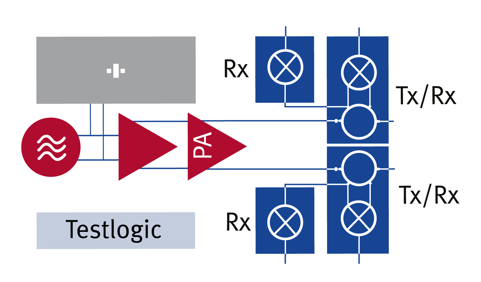
The Robert Bosch GmbH selected a radar chip from Infineon's RASIC(tm) (Radar System IC) product family for its next generation of automotive radar sensor systems LRR3. The radar chip enables smaller and more cost-effective radar systems than were possible with components based on the more expensive gallium-arsenide (GaAs) technology.
|
 |
The Robert Bosch GmbH selected a radar chip from Infineon's RASIC(tm) (Radar System IC) product family for its next generation of automotive radar sensor systems LRR3. The radar chip enables smaller and more cost-effective radar systems than were possible with components based on the more expensive gallium-arsenide (GaAs) technology.
|
Frequency Modulated Continuous Wave (FMCW) Radars Have Advantages Over Pulse Doppler Radars For Ground Surveillance
Ground Surveillance Radars can build a virtual wall around facilities or on a border. They provide operators and agents more response time to access, prioritize and apprehend intruders. They provide wide area surveillance and tracking over a large, 360 degree area, directing responders even after an intrusion has occurred. But, all GSR technologies are not the same. There are two primary GSR technologies - Pulsed Doppler radar technology and Frequency Modulated Continuous Wave (FMCW) radar technology. Most Pulsed Doppler radars are derivatives of legacy military battlefield radar being applied for wide area surveillance, while a new generation of FMCW radar technology was developed for wide area surveillance, site security and force protection. It was specifically developed to detect and track walking personnel. FLIR radars use FMCW radar technology.
Frequency Modulated Continuous Wave (FMCW) Radars
FMCW radars operate on the imaging principle; that is, they break up the background into small segments, or resolution cells, and then measure changes in the signal return from each cell to detect small targets, such as walking people. Typical resolutions for long range FMCW radars are less than 1 meter in range and less then 1 degree in azimuth. The smaller the cell the easier it is to detect and track a target. FMCW operation is independent of the speed or direction of travel of the target, only its size with respect to the resolution cell in which it is located. Modern FMCW radars can detect people moving at near zero speed and walking in any direction with respect to the radar.
Pulse Doppler (PD) Radars
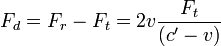
Pulse Doppler radars operate on the Doppler principle, which states that all moving objects will exhibit a frequency shift from the transmitted signal to the received signal, which is proportional to the speed of the target in the direction of the radar. If a target is walking directly toward the radar at 3 MPH, the radar will detect a frequency difference in the received signal and declare that a 3 MPH target has been detected. If the target is walking at 45 degree angle to the radar, the Doppler signal will be 3 MPH times the cosine of the angle, or about 2.1 MPH.
However, background clutter like trees and bushes also have some apparent speed when the wind blows. In order not to have a large number of false alarms, that low speed signal return from the clutter must be filtered out. A virtual velocity threshold (blind speed) is created below which targets will not be reliably detected. That means that some slowly moving targets could be filtered out along with the clutter. It also means that higher speed targets moving “across” the radar beam may be filtered out because speed only generates a Doppler signal proportional to the incoming or outgoing speed, which is called radial speed (approaching or receding in the beam).
Implications of Using Doppler as the Detection Technique
A fundamental deficiency exists such that wide area surveillance systems using Pulse Doppler radars have large areas where “slow” targets will not be detected. In fact, if an intruder walks at a speed somewhat below the velocity threshold (defined as the "blind speed") of the radar, it doesn’t matter in what direction the intrusion takes place, the intruder will likely not be detected at all – the intruder can simply walk through the perimeter or across the border and the radar will not detect the target. Alternatively, an intruder can walk between two radars spaced along a border and will be moving across the beams, or tangentially to each radar, and therefore, can walk at a higher speed than the velocity threshold, and still not be detected. This deficiency gives the intruders a major advantage. Those familiar with border operations know that intruders learn to avoid areas where they are apprehended regularly. Thus, holes in coverage inherent to Pulsed Doppler radars will be found and exploited, nullifying the very purpose of the radars. Changing the spacing or offsetting radars in latitude will somewhat change the shape of the non-detect zones, but will not eliminate the deficiency.
In summary, PD radars have an inherent flaw when used in ground surveillance applications. There is a conflicting trade off between minimizing clutter returns and the minimum detection speed of the target. Most PD radars will never detect at speeds less than 1.5 miles per hour (a distinct probability with walkers carrying 50 pounds or more of contraband).
The FMCW Advantage - Summary
The benefits of FMCW over other technologies such as pulse Doppler (PD) are numerous:
- FMCW is less complex, safer and lower cost than PD
- FMCW gives low false alarm rates
Proven in Government testing - The only radars to pass stringent U.S. Air Force false alarm testLess likely to alarm with wind blown objects --- grass and leaves, rain- One FMCW installation has 31 radars netted together using only one operator
- FMCW sees a higher percentage of valid targets
- Won’t miss slower targets or tangential ones – no holes in coverage – no one penetrates
- Smaller beamwidth for better pointing of cameras

Continuous-wave radar is a type of radar system where a known stable frequency continuous-wave radio energy is transmitted and then received from any reflecting objects.[1] Continuous-wave (CW) radar uses Doppler, which renders the radar immune to interference from large stationary objects and slow moving clutter. [2]
CW radar systems are used at both ends of the range spectrum.
- Inexpensive radio-altimeters, proximity sensors and sport accessories that operate from a few dozen feet to several kilometers
- Costly early-warning CW angle track (CWAT) radar operating beyond 100 km for use with surface-to-air missile systems

http://gs.flir.com/surveillance-products/surveillance-technology/frequency-modulated-continuous-wave-radars
http://www.ll.mit.edu/news/iapradarcourse.html
http://www.infineon.com/cms/en/corporate/press/news/releases/2008/INFATV200812-015.html
http://www.elva-1.com/products/industrial/FMCW_radar_front-end_200mW.html
http://www.fas.org/man/dod-101/navy/docs/es310/cwradar/cwradar.htm
http://www.slideshare.net/tobiasotto/principle-of-fmcw-radars
http://demonstrations.wolfram.com/FrequencyModulatedContinuousWaveFMCWRadar/
http://en.wikipedia.org/wiki/Continuous-wave_radar
Operation
The main advantage of CW radar is that energy is not pulsed so these are much simpler to manufacture and operate. They have no minimum or maximum range, although the broadcast power level imposes a practical limit on range. Continuous-wave radar maximize total power on a target because the transmitter is broadcasting continuously.
The military uses continuous-wave radar to guide semi-active radar homing (SARH) air-to-air missiles, such as the U.S. AIM-7 Sparrow and standard missile. The launch aircraft illuminates the target with a CW radar signal, and the missile homes in on the reflected radar waves. Since the missile is moving at high velocities relative to the aircraft, there is a strong Doppler shift. Most modern air combat radars, even pulse Doppler sets, have a CW function for missile guidance purposes.
Maximum distance in a continuous-wave radar is determined by the overall bandwidth and transmitter power. This bandwidth is determined by two factors.
- Transmit energy density (watts per Hertz)
- Receiver filter size (bandwidth divided by the total number of filters)
Doubling transmit power increases distance performance by about 20%. Reducing the total FM transmit noise by half has the same effect.
Frequency domain receivers used for continuous-wave Doppler radar receivers are very different from conventional radar receivers. The receiver consists of a bank of filters, usually more than 100. The number of filters determines the maximum distance performance.
Doubling the number of receiver filters increases distance performance by about 20%. Maximum distance performance is achieved when receiver filter size is equal to the maximum FM noise riding on the transmit signal. Reducing receiver filter size below average amount of FM transmit noise will not improve range performance.
A CW radar is said to be matched when the receiver filter size matches the RMS bandwidth of the FM noise on the transmit signal.
[edit]Types
There are two types of continuous-wave radar: unmodulated continuous-wave and modulated continuous-wave.
[edit]Unmodulated continuous-wave

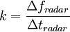
This kind of radar can cost less than $100 (2012). Return frequencies are shifted away from the transmitted frequency based on theDoppler effect when objects are moving. There is no way to evaluate distance. This type of radar is typically used with competition sports, like golf, tennis, baseball, and NASCAR racing.
The Doppler frequency change depends on the speed of light in the air (c’ is slightly slower than in vacuum) and v the speed of the target:[3]

The Doppler frequency is thus:[4]
Since the usual variation of targets' speed of a radar is much smaller than c' ( ), it is possible to simplifiy with
  :
:
), it is possible to simplifiy with :
Continuous-wave radar with no FM modulation only detects moving targets, as stationary targets (along the line of sight) will not cause a Doppler shift. Reflected signals from stationary and slow-moving objects are masked by the transmit signal, which overwhelms reflections from slow-moving objects during normal operation.
[edit]Modulated continuous-wave
Frequency-modulated continuous-wave radar (FM-CW) is a short range measuring radar set capable of determining distance. This increases reliability by providing distance measurement along with speed measurement, which is essential when there is more than one source of reflection arriving at the radar antenna. This kind of radar is often used as “radar altimeter” to measure the exact height during the landing procedure of aircraft.[5] It is also used as early-warning radar, and proximity sensors. Doppler shift is not always required for detection when FM modulation is used.
In this system the transmitted signal of a known stable frequency continuous wave varies up and down in frequency over a fixed period of time by a modulating signal. Frequency deviation on the receive signal increases with distance. This smears out, or blurs, the Doppler signal. Echoes from a target are then mixed with the transmitted signal to produce a beat signal which will give the distance of the target after demodulation.
A variety of modulations is possible, the transmitter frequency can slew up and down as follows :
- Sine wave, like air raid siren
- Sawtooth wave, like the chirp from a bird
- Triangle wave, like police siren in the United States
- Square wave, like police siren in the United Kingdom
Range demodulation is limited to 1/4 wavelength of the transmit modulation. Instrumented range for 100 Hz FM modulation would be 500 km. That limit depends upon the type of modulation and demodulation. The following generally applies.

The radar will report incorrect distance for reflections from distances beyond the instrumented range, such as from the moon. FMCW range measurements are only reliable to about 60% of the instrumented range, or about 300 km for 100 Hz FM modulation.
[edit]Sawtooth Frequency Modulation

 ) error can be ignored and the transmitters power is linearly frequency modulated, then the time delay (
 ) is proportionally the difference of the transmitted and the received signal (
 ) at any time.
Sawtooth modulation is the most used in FM-CW radars where range is desired for objects that lack rotating parts. Range information is mixed with the Doppler velocity using this technique. Modulation can be turned off on alternate scans to identify velocity using unmodulated carrier frequency shift. This allows range and velocity to be found with one radar set. Triangle wave modulation can be used to achieve the same goal.
As shown in the figure the received waveform (green) is simply a delayed replica of the transmitted waveform (red). The transmitted frequency is used to down-convert the receive signal to baseband, and the amount of frequency shift between the transmit signal and the reflected signal increases with time delay (distance). The time delay is thus a measure of the range; a small frequency spread is produced by nearby reflections, a larger frequency spread corresponds with more time delay and a longer range.
With the advent of modern electronics, digital signal processing is used for most detection processing. The beat signals are passed through ananalog-to-digital converter, and digital processing is performed on the result. As explained in the literature, FM-CW ranging for a linear ramp waveform is given in the following set of equations:[5]
-
-
- where
 is the radar frequency sweep amount and
  is the time to complete the frequency sweep.
- where
-
Then,  , rearrange to a more useful:
, rearrange to a more useful:-
 , where
  is the round trip time of the radar energy.
It is then a trivial matter to calculate the physical one-way distance for an idealized typical case as:

-
-
- where
 is the speed of light in any transparent medium of refractive index n (n=1 in vacuum and 1.0003 for air).
- where
-
For practical reasons, receive samples are not processed for a brief period after the modulation ramp begins because incoming reflections will have modulation from the previous modulation cycle. This imposes a range limit and limits performance.

[edit]Sinusoidal Frequency Modulation

Sinusoidal FM modulation is used when both range and velocity are required simultaneously for complex objects with multiple moving parts like turbine fan blades, helicopter blades, or propellers. This processing reduces the effect of complex spectra modulation produced by rotating parts that introduce errors into range measurement process.
This technique also has the advantage that the receiver never needs to stop processing incoming signals because the modulation waveform is continuous with no impulse modulation.
Sinusoidal FM modulation is eliminated completely by the receiver for close in reflections because the transmit frequency will be the same as the frequency being reflected back into the receiver. The spectrum for more distant objects will contain more modulation. The amount of spectrum spreading caused by modulation riding on the receive signal is proportional to the distance to the reflecting object.
The time domain formula for FM modulation is:

-
- where
 (modulation index)
- where
A time delay is introduced in transit between the radar and the reflector.

-
- where
 time delay
- where
The detection process down converts the receive signal using the transmit signal. This eliminates the carrier.


The Carson bandwidth rule can be seen in this equation, and that is a close approximation to identify the amount of spread placed on the receive spectrum:


Receiver demodulation is used with FMCW similar to the receiver demodulation strategy used with pulse compression. This takes place before Doppler CFAR detection processing. A large modulation index is needed for practical reasons.
Practical systems introduce reverse FM modulation on the receive signal using digital signal processing before the Fast Fourier Transform process is used to produce the spectrum. This is repeated with several different demodulation values. Range is found by identifying the receive spectrum where width is minimum.
Practical systems also process receive samples for several cycles of the FM modulation in order to reduce the influence of sampling artifacts.
[edit]Configurations

There are two different antenna configurations used with continuous-wave radar: monostatic radar, and bistatic radar.
[edit]Monostatic
The radar receive antenna is located nearby the radar transmit antenna in monostatic radar.
Feed-through null is typically required to eliminate bleed-through between the transmitter and receiver to increase sensitivity in practical systems. This is typically used with continuous-wave angle tracking (CWAT) radar receivers that are interoperable with surface to air missile systems.
Interrupted continuous-wave can be used to eliminate bleed-through between the transmit and receive antenna. This kind of system typically takes one sample between each pair of transmit pulses, and the sample rate is typically 30 kHz or more. This technique is used with the least expensive kinds of radar, such as those used for traffic monitoring and sports.
FM-CW radars can be built with one antenna using either a circulator, or circular polarization.
[edit]Bistatic
The radar receive antenna is located far from the radar transmit antenna in bistatic radar. The transmitter is fairly expensive, while the receiver is fairly inexpensive and disposable.
This is typically used with semi-active radar homing including most surface to air missile systems. The transmit radar is typically located near the missile launcher. The receiver is located in the missile.
The transmit antenna illuminates the target in much the same way as a search light. The transmit antenna also issues an omnidirectional sample.
The receiver uses two antennas – one antenna aimed at the target and one antenna aimed at the transmit antenna. The receive antenna that is aimed at the transmit antenna is used to develop the feed-through null, which allows the target receiver to operate reliably in or near the main beam of the antenna.
Most modern systems FM-CW radars use one transmitter antenna and multiple receiver antennas. Because the transmitter is on continuously at effectively the same frequency as the receiver, special care must be exercised to avoid overloading the receiver stages.
[edit]Monopulse
Main article: Monopulse radar
Monopulse antennas produce angular measurements without pulses or other modulation. This technique is used in semi-active radar homing.
[edit]Leakage
The transmit signal will leak into the receiver on practical systems. Significant leakage will come from nearby environmental reflections even if antenna components are perfect. As much as 120dB of leakage rejection is required to achieve acceptable performance.
Three approaches can be used to produce a practical system that will function correctly.
- Null
- Filter
- Interruption
Null and filter approaches must be used with bistatic radar, like semi-active radar homing, for practical reasons because side-lobes from the illumination radar will illuminate the environment in addition to the main-lobe illumination on the target. Similar constraints apply to ground based CW radar. This adds cost.
Interruption applies to cheap hand held mono-static radar systems (police radar and sporting goods). This is impractical for bistatic systems because of the cost and complexity associated with coordinating time with nuclear precision in two different locations.
Principle of FMCW radar
- 1. ATMOS Principle of FMCW Radars Tobias Otto Delft University of Technology Remote Sensing of the Environment
- 2. AT ContentsMOS I. Principle of FMCW radar II. FMCW radar signal processing III. Block diagram of an FMCW radar for precipitation measurements Delft University of Technology Remote Sensing of the Environment
- 3. AT Principle of FMCW radarMOS frequency-modulated continuous-wave A radar transmitting a continuous carrier modulated by a periodic function such as a sinusoid or sawtooth wave to provide range data (IEEE Std. 686-2008). Modulation is the keyword, since this adds the ranging capability to FMCW radars with respect to unmodulated CW radars. We will concentrate in this talk on linear FMCW radar (LFMCW). frequency amplitude f0 time up-chirp time Delft University of Technology Remote Sensing of the Environment
- 4. AT Principle of FMCW radarMOS frequency-modulated continuous-wave A radar transmitting a continuous carrier modulated by a periodic function such as a sinusoid or sawtooth wave to provide range data (IEEE Std. 686-2008). Modulation is the keyword, since this adds the ranging capability to FMCW radars with respect to unmodulated CW radars. We will concentrate in this talk on linear FMCW radar (LFMCW). frequency amplitude down-chirp f0 time time Delft University of Technology Remote Sensing of the Environment
- 5. AT Principle of FMCW radarMOS frequency-modulated continuous-wave A radar transmitting a continuous carrier modulated by a periodic function such as a sinusoid or sawtooth wave to provide range data (IEEE Std. 686-2008). Modulation is the keyword, since this adds the ranging capability to FMCW radars with respect to unmodulated CW radars. We will concentrate in this talk on linear FMCW radar (LFMCW). frequency amplitude triangular f0 time time Delft University of Technology Remote Sensing of the Environment
- 6. A T Single target M O S Radar range R frequency frequency excursion,sweep bandwidth Bsweep time sweep time Ts Delft University of Technology Remote Sensing of the Environment
- 7. A T Single target M O S Radar range R frequency td fb Ts Bsweep frequency excursion, cTs fb Rsweep bandwidth Bsweep beat frequency fb 2 Bsweep time sweep time Ts 2R td modulus of c the spectrum receiver Fourier output transformation range time fb frequency Delft University of Technology Remote Sensing of the Environment
- 8. AT Moving single targetMOS A moving target induces a radial velocity vr f fD Doppler frequency shift Radar 2vr fD range R with the radar wavelength λ. frequency sweep bandwidth Bsweep frequency excursion, beat frequency The beat frequency is not only related to the range fD of the target, but also to time its relative radial velocity sweep time Ts with respect to the radar. Delft University of Technology Remote Sensing of the Environment
- 9. AT Moving single targetMO Beat frequency componentsS due to range and Doppler radial velocity vr frequency shift: f fD Radar Bsweep 2 R fb Ts c 2vr range R fD frequency that are superimposed as fbu fb fd fbd fb fd so range and radial velocity can be obtained as time cTs R f bd fbubeat frequency 4 Bsweep vr fbd fbu fbu fbd fbu fbd 4 time Delft University of Technology Remote Sensing of the Environment
- 10. AT Atmospheric FMCW radarMOS Radar range R When the expected Doppler frequency shift of the target has a negligible effect on the range extraction from the beat frequency, it can be estimated by comparing the phase of the echoes of successive sweeps, e.g. for meteorological applications. 2 the phase of the received signal is r t 2R the change of the phase of the received signal with time is given by d r 4 dR 4 vr dt dt and the change of the phase of the received signal from sweep to sweep is given as r 4 r vr vr Ts Ts 4 Delft University of Technology Remote Sensing of the Environment
- 11. AT ContentsMOS I. Principle of FMCW radar II. FMCW radar signal processing III. Block diagram of an FMCW radar for precipitation measurements Delft University of Technology Remote Sensing of the Environment
- 12. AT FMCW radar signal processingMOS frequency time FFT FFT FFT FFT range range FFT time Doppler frequency FFT .. fast Fourier transformation Delft University of Technology Remote Sensing of the Environment
- 13. AT FMCW radar signal processingMO frequencyS spectrogram of the received power range time in-phase quadrature component component samples window function sweeps samples 2D FFT Doppler frequency sweeps Data: IDRA, TU Delft Delft University of Technology Remote Sensing of the Environment
- 14. AT ContentsMOS I. Principle of FMCW radar II. FMCW radar signal processing III. Block diagram of an FMCW radar for precipitation measurements Delft University of Technology Remote Sensing of the Environment
- 15. AT General block diagram of an FMCW radarMOS modulated power high-power oscillator divider microwave amplifier radar control and amplifier and low-noise amplifier mixer signal processing low-pass filter and filtering beat frequency fb Delft University of Technology Remote Sensing of the Environment
- 16. AT IDRA – TU Delft IRCTR Drizzle radarMOS Specifications CESAR – Cabauw Experimental Site for Atmospheric Research • 9.475 GHz central frequency • FMCW with sawtooth modulation • transmitting alternately horizontal and vertical polarisation, receiving simultaneously the co- and the cross-polarised component • 20 W transmission power • 102.4 µs – 3276.8 µs sweep time • 2.5 MHz – 50 MHz Tx bandwidth • 60 m – 3 m range resolution • 1.8 antenna half-power beamwidth Reference J. Figueras i Ventura: “Design of a High Resolution X-band Doppler Polarimetric Weather Radar”, PhD Thesis, TU Delft, 2009. (online available at http://repository.tudelft.nl) Near real-time display: http://ftp.tudelft.nl/TUDelft/irctr-rse/idra IDRA is mounted on top of the 213 m high Processed and raw data available at: meteorological tower. http://data.3tu.nl/repository/collection:cabauw Delft University of Technology Remote Sensing of the Environment
- 17. AT IDRA - IRCTR Drizzle radarMOS transmitter receiver Delft University of Technology Remote Sensing of the Environment
- 18. AT IDRA - IRCTR Drizzle radar (transmitter)MOS transmitter - GPS stabilised 10 MHz oscillator, for synchronisation of the whole system and data timestamp - direct digital synthesizer (DDS) that generates the sawtooth modulation (other waveforms can be easily programmed) - first up-conversion to the 350-400 MHz band, filtering and amplification / a power splitter provides the signal reference for the down-conversion in the receiver - second up-conversion to the radar frequency 9.45 – 9.5 GHz (X-band) - switch for transmitting either horizontal or vertical polarisation, and high-power solid-state microwave amplifiers Delft University of Technology Remote Sensing of the Environment
- 19. AT IDRA - IRCTR Drizzle radar (transmitter)MOS transmitter receiver - GPS stabilised 10 MHz oscillator, for synchronisation of the whole system and data timestamp - direct digital synthesizer (DDS) that generates the sawtooth modulation, other waveforms can be easily programmed - first up-conversion to the 350-400 MHz band, filtering and amplification / a power splitter provides the signal reference for the down-conversion in the receiver - second up-conversion to the radar frequency 9.45 – 9.5 GHz (X-band) - switch for transmitting either horizontal or vertical polarisation, and high-power solid-state microwave amplifier Delft University of Technology Remote Sensing of the Environment
- 20. AT IDRA - IRCTR Drizzle radar (receiver)MO - two-channel receiver to receive simultaneously the horizontal and vertical polarised echoes,S that first undergo the low noise amplification and first filtering stage - first down-conversion to the 350-400 MHz band followed by filtering and amplification - I/Q receiver, i.e. the received signal is splitted and mixed with 90 phase difference realisations of the transmitted signal at 400 MHz in order to obtain the in-phase and the quadrature-phase components of the received signal - after the analog-to-digital conversion, the received signal is sent to the radar control computer for signal processing receiver Delft University of Technology Remote Sensing of the Environment
- 21. ATMOS Principles and Applications of FMCW Radars Tobias Otto e-mail t.otto@tudelft.nl web http://atmos.weblog.tudelft.nl Delft University of Technology Remote Sensing of the Environment
No comments:
Post a Comment